|
|
||||||||||||||||||||||||||||||||||||||||||||||||||||||
|
|
|||||||||||||||||||||||||||||||||||||||||||||||||||||
|
||||||||||||||||||||||||||||||||||||||||||||||||||||||
|
|
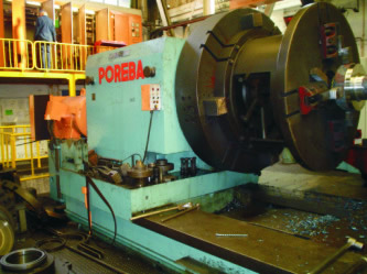
Both
CNC carriages were required to behave independently of each other, but share
control of the spindle. Carriage 1 was to be given master control, with
Carriage 2 able to control when Carriage 1 was either switched off or disabled.
When neither of the CNC carriages were in use, then the boring carriage would also be allowed to control spindle speed. A PLC system within the main electrical cabinets would control the interlocks between the 3 main control stations, as well as all the secondary machine functions (hydraulics, lubrication, tailstock motor..etc). A Mitsubishi Q Series PLC system was selected as the most appropriate solution. |
|||||||||||||||||||||||||||||||||||||||||||||||||||||
|
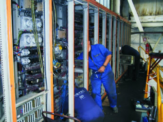
New electrical drawings were completed, and the original wiring numbers were all carefully noted and reallocated. As much assembly as possible of the new electrical cabinets were completed in Robtec's workshop beforehand, in order to save time when on site. Once ready, the disassembly of the old electrical cabinets could begin. All incoming wires were carefully labeled and bundled according to their location to save time when wiring into the new cabinets later on. |
 |
|||||||||||||||||||||||||||||||||||||||||||||||||||||
 |
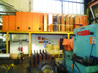
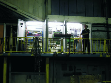
The old electrical cabinets were removed with the use of a crane, and the new ones mounted on the mezzanine level in their place. The new cabinets only take up half the space of the original ones as a great deal of the old relay logic is replaced by the PLC. In addition, the drives for the axis carriages were being moved down into smaller electrical cabinets on the carriages themselves. During the installation, Robtec was able to provide multiple engineers on-site to assist with the wiring. This allowed the cabinets on the CNC carriages and the main electrical cabinets to be wired simultaneously. |
|||||||||||||||||||||||||||||||||||||||||||||||||||||
|
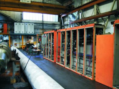
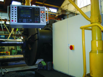
Towards the end of the second week, the most of the reassembly within the main electrical cabinets had been completed, and the incoming power cables could be reconnected. Carriage 1 (which had already had the CNC fitted) had been re-wired for the new system configuration. Carriage 2 had been fitted out with reader-heads, a reference switch and new optical scale along its X axis. The new cabinet and pendant unit had been installed, and wiring was continuing in preparation for the start of commissioning during week 3. |
 |
|||||||||||||||||||||||||||||||||||||||||||||||||||||
 |
The machine was ready for commissioning mid-way through the third week. The commissioning process took 1 week before Robtec engineers were happy to allow the operators to start to use the machine. Full training on the new system was provided, and the project completed within the allocated time-frame.
|
|||||||||||||||||||||||||||||||||||||||||||||||||||||